Robotic Ultrasound Scanning
What I did
- Led the RealSense integration and point-cloud pipeline that computes surface normals for automatic probe alignment
- Built the Tkinter control GUI for all six fundamental ultrasound motions
- Collaborated on KDL inverse kinematics, force control and offset correction
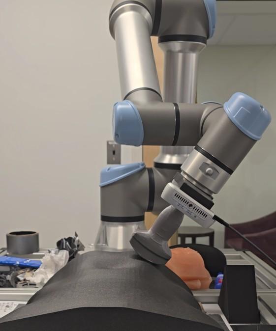
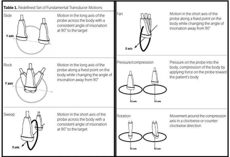
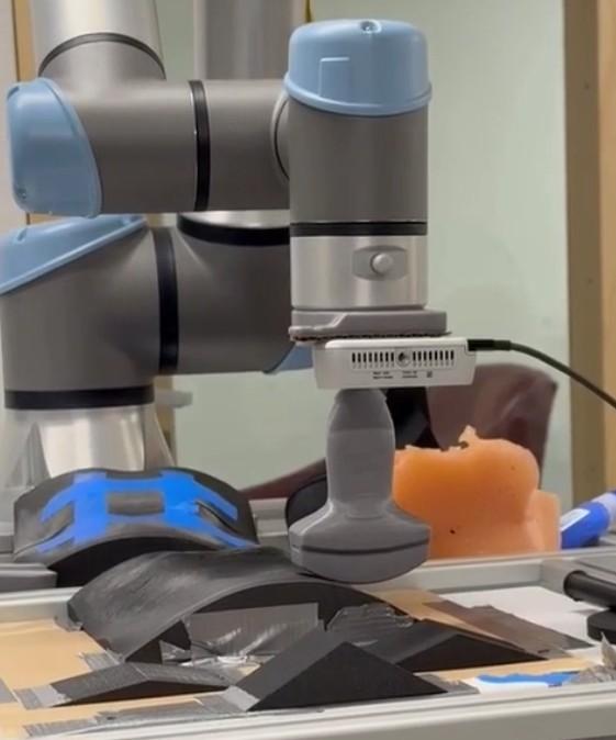
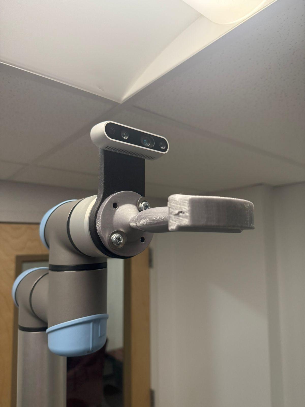
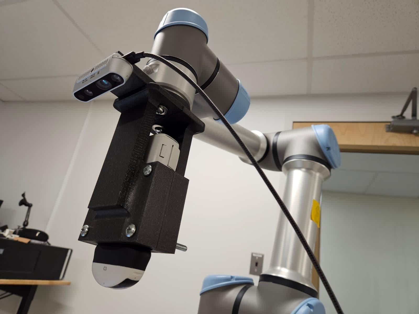
Our team developed a semi-autonomous robotic ultrasound system using a UR5e robot arm equipped with a RealSense depth camera and Clarius C3 HD3 ultrasound probe. The system can execute all six fundamental transducer motions (Slide, Sweep, Rock, Fan, Rotate, Compression) while automatically maintaining probe orientation normal to the body surface through real-time point cloud processing and force-feedback control.
My primary contributions were developing the TKinter-based control GUI and leading the RealSense camera integration with the complete point cloud processing pipeline. The GUI enables intuitive operator control through button presses, while the vision system processes depth data at 1280×720p resolution to compute surface normals for automatic probe alignment. The system achieved 0.5° mean angular error on flat surfaces and maintained contact force within the 0.5–2 N safety range across anthropomorphic contours.
Problem Statement
- Need: Ultrasound demand increased 55.1% over a decade while sonographer workforce grew only 43.6%, leaving a staffing gap
- Ergonomic burden: 90% of sonographers develop work-related musculoskeletal disorders from repetitive probe positioning and sustained postures
- Technical challenge: Ultrasound imaging requires precise probe orientation perpendicular to tissue surfaces while maintaining consistent contact force, difficult to automate on complex body contours
We wanted to see whether a semi-autonomous system could perform the basic ultrasound motions while keeping the probe at the right angle and a safe contact force.
Methodology
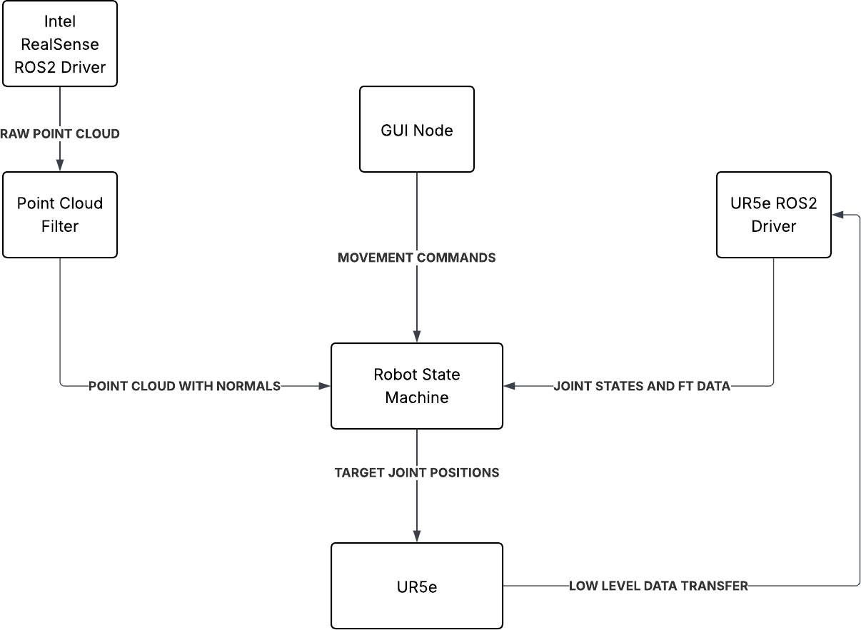
The project followed a modular ROS2 architecture integrating depth perception, control interface, and motion planning.
System Architecture
The system consists of four ROS2 packages working together. The ultrasound_description package contains a modified URDF representing the UR5e with RealSense camera attached, along with launch files for hardware interfacing. The pc_filter package handles point cloud processing, the control_gui provides operator interface, and the ultrasound_state_machine manages trajectory generation using KDL inverse kinematics.
Point Cloud Processing & Normal Estimation
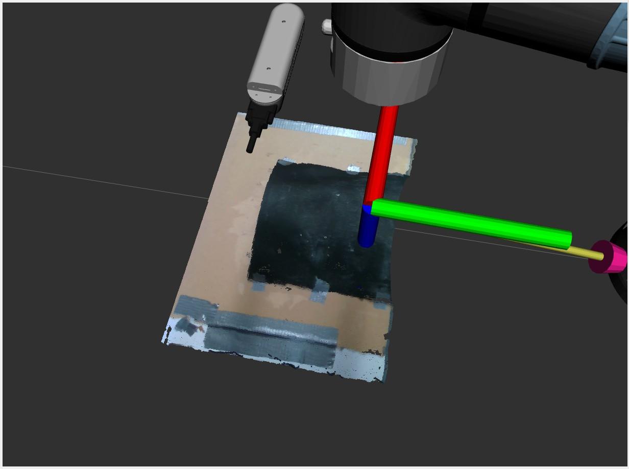
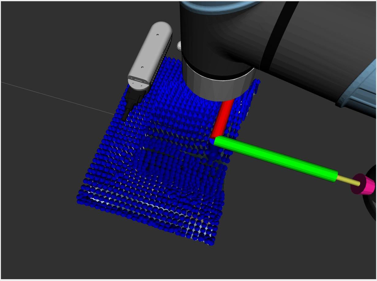
The RealSense camera captures depth data at 1280×720p @ 6fps resolution. I developed the point cloud filtering pipeline that removes Cartesian outliers, downsamples the cloud to reduce processing overhead, and transforms points from the RealSense optical frame to the UR5e base frame. Surface normals are then computed and published as a PointCloud2 message for use by the state machine in automatic orientation alignment.
Control GUI Development
I created a TKinter-based GUI using RCLPY that allows operators to control the robot through intuitive button presses. The GUI publishes ROS2 Twist messages containing Cartesian displacement commands. Key modes include Free Move (unrestricted Cartesian motion), Contour Move (surface-constrained motion with automatic normal alignment), and automated Rock/Fan motions. A linear speed slider allows adjustment of movement rate.
Modes Control mode descriptions
- Free Move: Unrestricted Cartesian motion for positioning
- Contour Move: Surface-constrained motion with automatic normal alignment
- Rock: Automated tilting along probe's long axis
- Fan: Automated pivoting side-to-side while maintaining contact
- Sweep: Semi-automated lateral scanning with operator guidance
- Slide: Semi-automated linear motion along surface
Test Setup
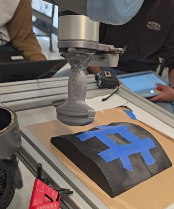
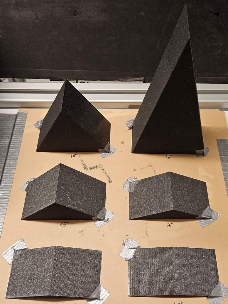
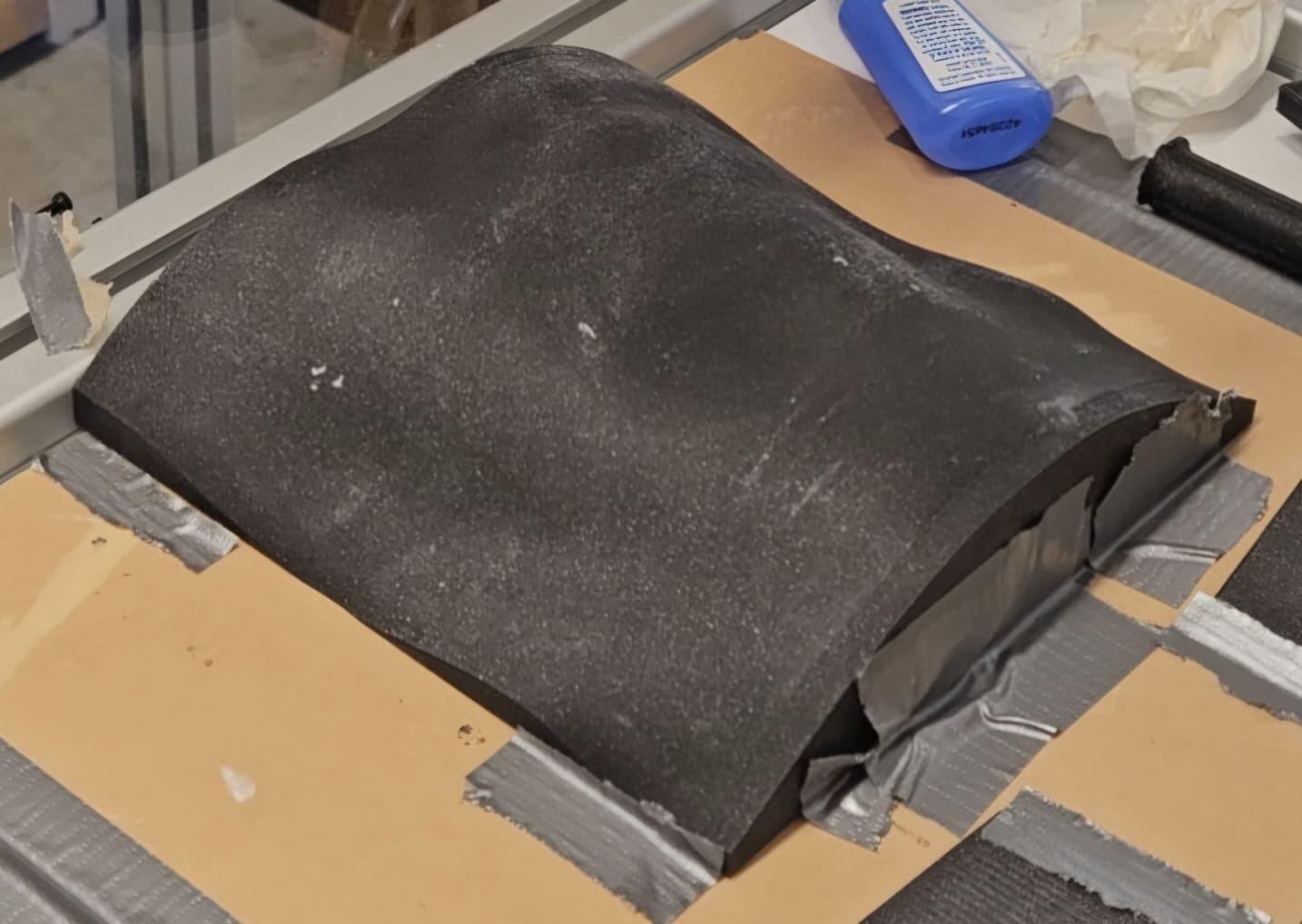
Testing was conducted on 3D printed wedges (0°, 30°, 45°) for angular accuracy, a 0.75-scale 3D printed torso for contour following, and a hydrogel phantom with the actual Clarius C3 HD3 probe for representative clinical testing. Force limits were adjusted for the softer hydrogel material to maintain contact without damage.
Results
Angular errors acceptable for smooth anthropomorphic surfaces encountered in clinical use.
For force control, experiments 1, 2 and 4 achieved mean forces of 1.14 N, 1.78 N, and 1.32 N respectively, all within the 0.5–2 N acceptable range for typical anthropomorphic contours. The system adapts to both hard (3D printed) and soft (hydrogel) surfaces through adjustable force limits.
Data Angular error analysis table
Angular Error Analysis Results (5 trials per slope angle)
| Slope | Trial 1 | Trial 2 | Trial 3 | Trial 4 | Trial 5 | Mean |
|---|---|---|---|---|---|---|
| 0° (flat) | 0.3° | 0.5° | 0.6° | 0.4° | 0.7° | 0.5° |
| 30° | 3.8° | 4.2° | 4.1° | 4.0° | 4.3° | 4.08° |
| 45° | 4.3° | 4.6° | 4.5° | 4.4° | 4.7° | 4.5° |
Findings Key results summary
- Demonstrated semi-autonomous contour following on 3D printed torso and hydrogel phantom
- Achieved 0.5° mean angular error on flat surfaces with 0.3° standard deviation
- Angular error of 4.08° mean on 30° slopes and 4.5° mean on 45° slopes, acceptable for smooth anthropomorphic surfaces
- Force control maintained within 0.5–2 N range for typical contours
- Automated Rock and Fan motions implemented
- Semi-automated Slide and Sweep motions with operator guidance
- System adaptable to both hard (3D printed) and soft (hydrogel) surfaces through adjustable force limits
Team Contributions & credits
I led RealSense camera integration and point cloud processing pipeline development, and designed the TKinter control GUI for all six fundamental ultrasound motions. Collaborated on KDL inverse kinematics, force control, and offset correction algorithms.
Team members: Adithya R N (3D printed phantoms, hydrogel fabrication, CAD), Manyu Garg (3D printed components, CAD), Rahul Kalpana Anwardeen (ultrasound_state_machine package).
Completed for EN.530.721 Medical Robotic System Design at Johns Hopkins University.
The Hardest Parts
The hardest parts to get right were the point-cloud processing and the force control.
Full Report
Complete technical report with methodology, implementation details, and results.