MRI Needle Insertion Robot
What I did
- Implemented inverse kinematics for the 3-stage pneumatic robot
- Built the MATLAB pipeline that finds vertebra boundaries in MRI data and plans the needle path
- Fixed coordinate-flip and scale errors in the image-to-robot transform, cutting error from about 15 mm to under 2 mm
Problem Statement
- Clinical need: Lumbar spine needle procedures (biopsies, epidural injections) require precise targeting between vertebrae to avoid nerve damage and bone contact
- MRI compatibility: Traditional robotic actuators use ferromagnetic components incompatible with MRI environments, limiting real-time image-guided intervention
The target was a pneumatic robot with an image-to-robot transform accurate to a millimetre or two, enough to place a needle between vertebrae.
Methodology
The project followed a complete image-guided intervention pipeline: MRI acquisition, then image processing, then path planning, then coordinate transformation, then robot control.
MRI Image Acquisition & Processing
MRI scans were processed using 3D Slicer software to select optimal slices showing fiducial markers and vertebrae contours clearly. Window-leveling was applied to maximize fiducial contrast for localization and reduce gray noise in vertebrae images for robust boundary detection. Images were exported at 256×256 resolution to match the coordinate conversion factor.
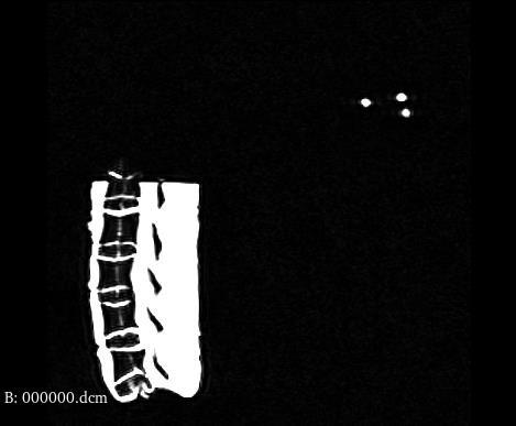
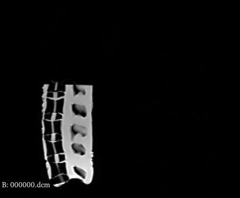
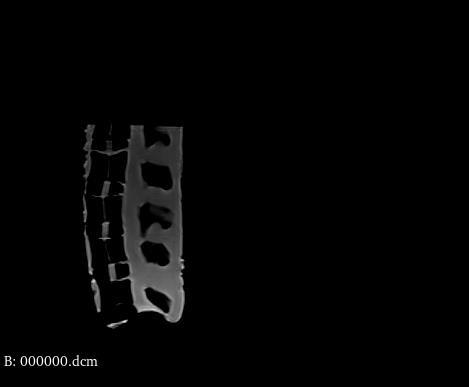
Process 3D Slicer workflow details
- Loaded MRI DICOM series and navigated to slice containing both robot fiducials and vertebrae
- Applied window-leveling to maximize fiducial marker contrast for accurate localization
- Separately window-leveled vertebrae images to reduce gray noise while preserving bone boundaries
- Exported images at 256×256 resolution for consistent pixel-to-mm conversion
Vertebrae Detection & Path Planning
MATLAB scripts performed morphological closing (imclose) followed by boundary detection (bwboundaries) to identify each vertebra. Region properties including centroids, area, and perimeter were computed using regionprops. For each intervertebral space (L1/L2 through L4/L5), the optimal needle path was calculated by averaging Y-values between upper and lower vertebrae boundaries, maximizing distance from bone.
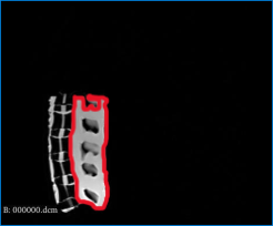
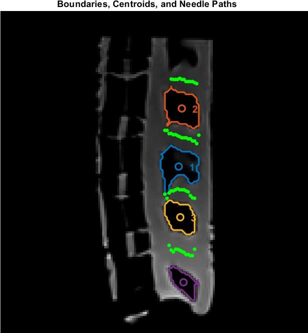
Algorithm Path computation details
- A custom script (
L1_vertebrae_code.m) handled the partially visible top vertebra by extracting only its lower boundary - For each intervertebral space, the algorithm computed the midline between adjacent vertebrae boundaries
- Entry point selected at skin surface; target point at disc center, maximizing clearance from bone
- Angled insertion paths demonstrated easier penetration than perpendicular approaches
Coordinate Transformation
A pipeline converted coordinates from 3D Slicer image space to real-world robot commands. The conversion factor was empirically measured as 1.20225 (corrected from the Slicer-provided 1.367). The transformation accounted for image orientation without flipping, handling coordinate conversion in the final robot command stage instead.
Key Bug Conversion factor error impact
The conversion factor error of 0.16 (1.367 − 1.20225) caused a 15mm X-offset and 7mm Y-offset at the first vertebral slot. This was the largest single source of positioning error, identified through systematic line-by-line code review during live demonstration debugging.
Inverse Kinematics & Robot Control
The 3-stage pneumatic system uses 2D inverse kinematics since height is fixed. Stage 1 controls Y-direction with a 70mm platform (stage_center = 35mm). Stage 2 controls rotation angle theta. Stage 3 controls needle insertion depth affecting both X and Y. Trigonometric calculations determine travel distances, which are then converted to motor steps.
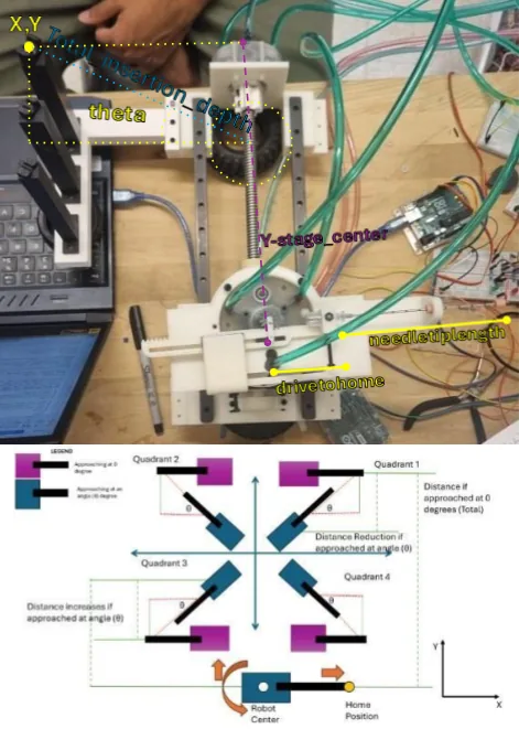
Stages 3-DOF actuation breakdown
- Stage 1: Y-axis translation: positions needle laterally relative to vertebral column
- Stage 2: Angular rotation (θ): orients needle angle for entry trajectory
- Stage 3: Needle insertion depth: controls penetration with half-speed operation for accuracy
System Integration & Debugging
Live demonstration revealed three bugs that were systematically identified through line-by-line code review and resolved:
Debug Log Systematic bug resolution
- Bug 1: Coordinate flip: X and Y coordinates were swapped in the transformation code, causing theta to be mirrored. Fixed by correcting variable assignment order.
- Bug 2: Conversion factor: Using Slicer-provided 1.367 instead of measured 1.20225 caused 15mm X-offset and 7mm Y-offset. Fixed by empirical measurement from fiducial distances.
- Bug 3: Theta reference: Reference line calculation using fiducial markers introduced angular errors (20° vs correct 10°). Simplified to horizontal reference (slope=0).
Test Setup
System validated through resistance force tests on silicone blocks and targeting tests on a 3D printed spine phantom model. The pneumatic robot operated at 25 psi with Stage 3 running at half speed for insertion accuracy.
Equipment Test setup components
- 3-stage pneumatic robot with MRI-compatible materials
- 3D Slicer for MRI image processing and slice selection
- MATLAB for path planning and robot command generation
- Silicone blocks for resistance force validation
- 3D printed spine phantom for targeting accuracy tests
- Team 5's robot (equipment assistance for some test footage)
Results
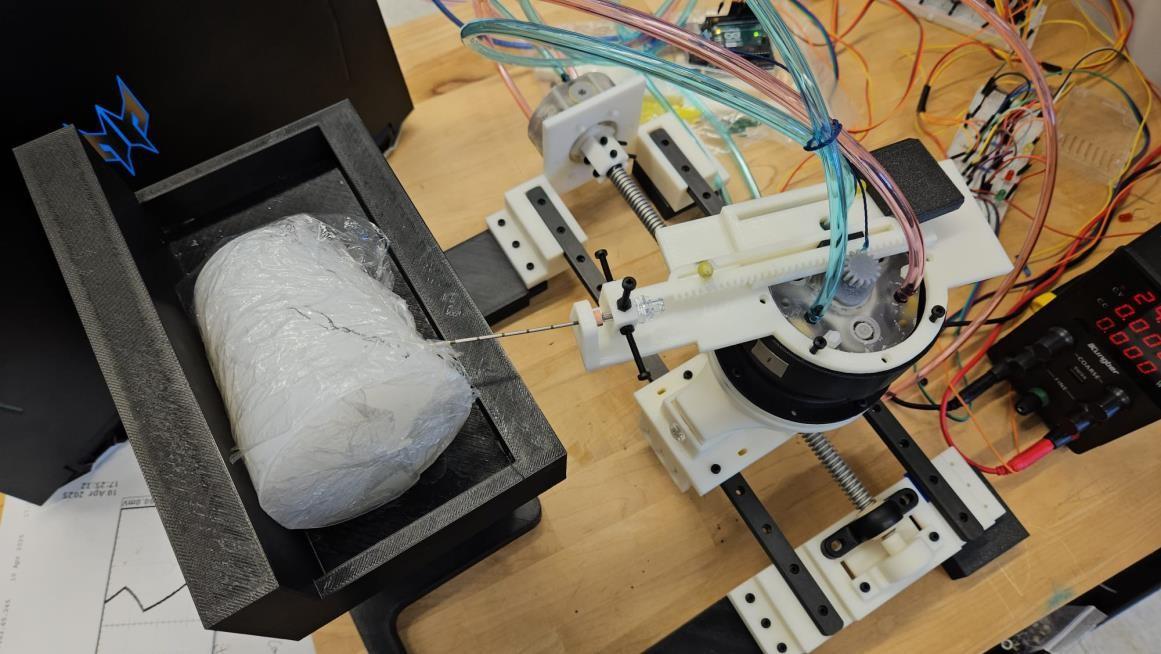
Post-debugging positioning accuracy achieved within a few millimeters across all 4 vertebral slots.
Data Computed needle path coordinates
Needle path coordinates computed in MATLAB image space (256×256), maximizing distance from vertebrae boundaries for safe insertion.
| Vertebral Path | Entry Point (x,y) | Target Point (x,y) |
|---|---|---|
| L1/L2 | (93, 105) | (81, 102.833) |
| L2/L3 | (92, 132) | (80, 128.5) |
| L3/L4 | (90, 157.75) | (79, 159) |
| L4/L5 | (92, 183) | (80, 181.167) |
Key Finding Debugging impact on accuracy
- Corrected conversion factor (1.20225 vs 1.367) eliminated 15mm X / 7mm Y positioning errors
- Simplified theta reference (horizontal line, slope=0) reduced angular error from 20° to 10°
- Angled needle insertion demonstrated easier penetration than perpendicular approach
- Final system achieved <2mm needle depth accuracy after Stage 3 speed optimization
Future Future work
- Improve part tolerancing to reduce wobble and mechanical errors affecting accuracy
- Enhance motor reliability to prevent step skipping during operation
- Develop more accurate conversion factor calculation method less sensitive to fiducial position variations
- Implement closed-loop feedback for real-time position correction
- Extend to 3D path planning with variable insertion height
How We Found the Bugs
We found the bugs by testing and calculating. For each move we worked out the value the robot should reach, measured how far off it actually was, and traced the difference back to its source. That's how the coordinate flip, the conversion factor and the angle reference each turned up.
Full Report
Lab report documenting the complete methodology, results, and analysis.
Team Contributions & credits
I developed the inverse kinematics calculations, MATLAB image processing pipeline for vertebrae boundary detection and path planning, and led the systematic debugging effort that identified and resolved three coordinate transformation bugs, achieving <2mm needle positioning accuracy.
Team collaboration with Date and RN (equal contribution). Equipment assistance from Team 5 for testing.
Course: EN.530.666 - Magnetically Actuated and MRI Compatible Robots, Johns Hopkins University - Whiting School of Engineering.