MEMS Inertial Sensors for ISRO
What I did
- Designed a dual-axis capacitive accelerometer and an accordion-like disk resonator gyroscope (ADRG) through parametric sweeps of beam, ring and electrode geometry
- Ran COMSOL eigenfrequency and electromechanical studies across five gyroscope topologies, with <5% error versus fabricated devices
- Prepared CleWin/KLayout fabrication layouts and co-authored the ICMNS 2024 paper
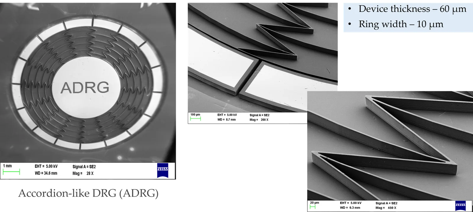
Over a two-year collaboration between IISc and ISRO, this project aimed to develop a complete MEMS Inertial Measurement Unit for space navigation applications. The IMU comprised two core sensors: a dual-axis capacitive accelerometer and an Accordion-like Disk Resonator Gyroscope (ADRG). Starting from an existing ring-and-spoke gyroscope concept, extensive parametric optimization was performed on both devices using COMSOL multiphysics simulations. Both devices were fabricated at CeNSE, with the gyroscope validated via laser Doppler vibrometry achieving <5% eigenfrequency error.
Problem Statement
- Need: ISRO required high-precision inertial sensors for space navigation applications
- Prior art: Existing DRG topologies (standard DRG, Honeycomb DRG (HDRG), Concentric DRG (CDRG), and Gear-tooth DRG (GDRG)) each advanced sensitivity incrementally but always traded electrode placement against mechanical performance
We set out to find a ring geometry that would raise mechanical sensitivity and quality factor without hurting noise performance or making the device harder to fabricate.
Methodology
The project followed a design-simulate-fabricate-test workflow spanning both accelerometer and gyroscope development.
Design & Simulation
Accelerometer Design
The MEMS accelerometer employs a proof mass suspended by folded-beam flexures with interdigitated comb-drive electrodes for differential capacitive sensing.
Optimization Accelerometer optimization parameters
A parametric study varied beam width (5, 6, 7, 8 µm) and out-of-plane thickness (10, 20, 30, 60 µm) to optimize:
- Eigenfrequency (~3 kHz target)
- Displacement sensitivity
- Capacitance sensitivity (ΔC/g)
- Cross-axis sensitivity
- Quality factor
- Brownian noise equivalent acceleration
Gyroscope Topology Comparison
Five DRG topologies were evaluated using COMSOL Multiphysics. The novel Accordion-like DRG (ADRG) introduces accordion-shaped spoke connections that increase mechanical compliance while maintaining structural integrity.
Held constant across all five topologies for a fair comparison.
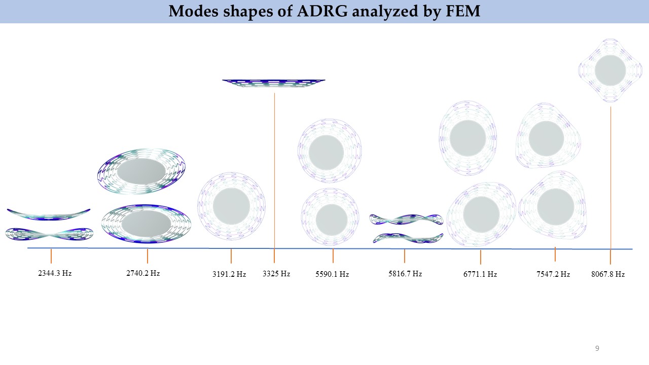
Note Why accordion spokes?
Mechanical Sensitivity (×10⁻⁶ µm/rad/s):
Data Complete topology comparison table
Disk Resonator Gyroscope Topology Comparison (9 rings, 8mm OD, 10µm ring width, 60µm thickness)
| DRG Type | Freq (Hz) | Q (k) | ΔC₀/C₀ (%) |
|---|---|---|---|
| DRG | 12,720 | 103.62 | 14.37 |
| HDRG | 11,306 | 105.42 | 16.39 |
| CDRG | 12,611 | 99.99 | 26.36 |
| GDRG | 14,761 | 91.58 | 29.40 |
| ADRG | 6,771 | 181.55 | 46.44 |
Fabrication
Mask Layout Generation
Once mechanical and electrode parameters were finalized through simulation, designs were converted into semiconductor fabrication mask layouts.
- CleWin: initial layout design and layer definition
- KLayout: advanced editing and DRC (Design Rule Check) verification
SOI Microfabrication
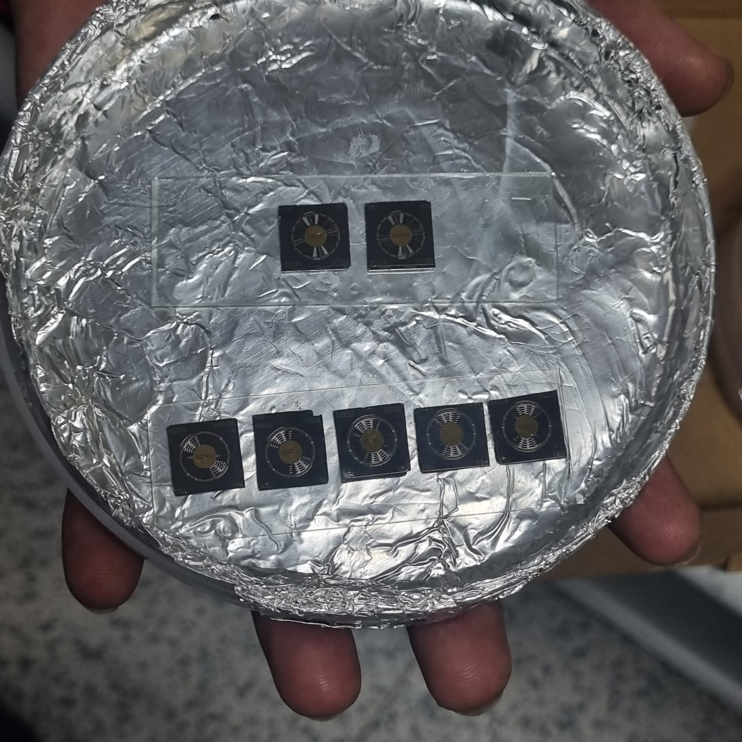
Devices were fabricated at the Centre for Nano Science and Engineering (CeNSE) at IISc using SOI-based surface micromachining.
Wire Bonding
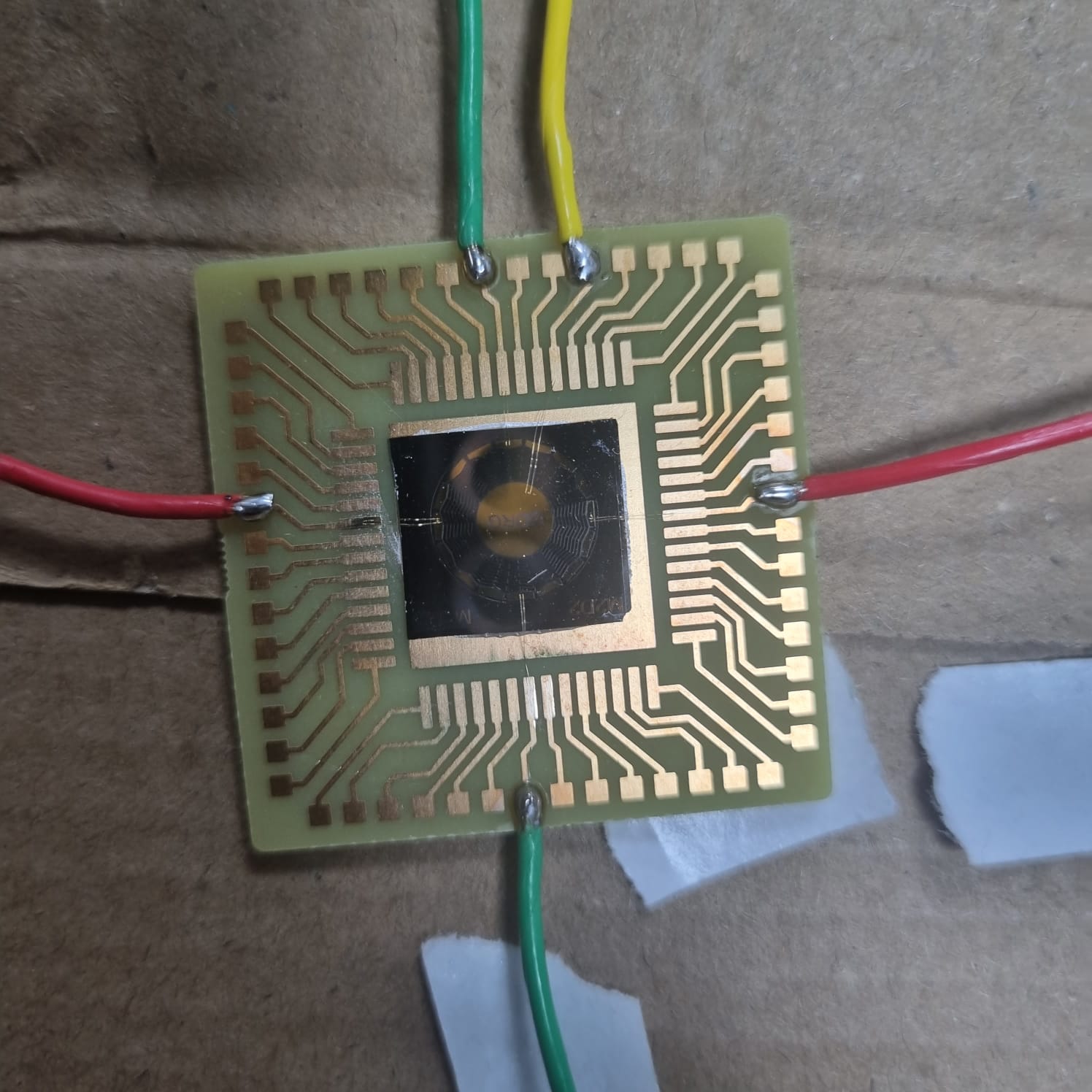
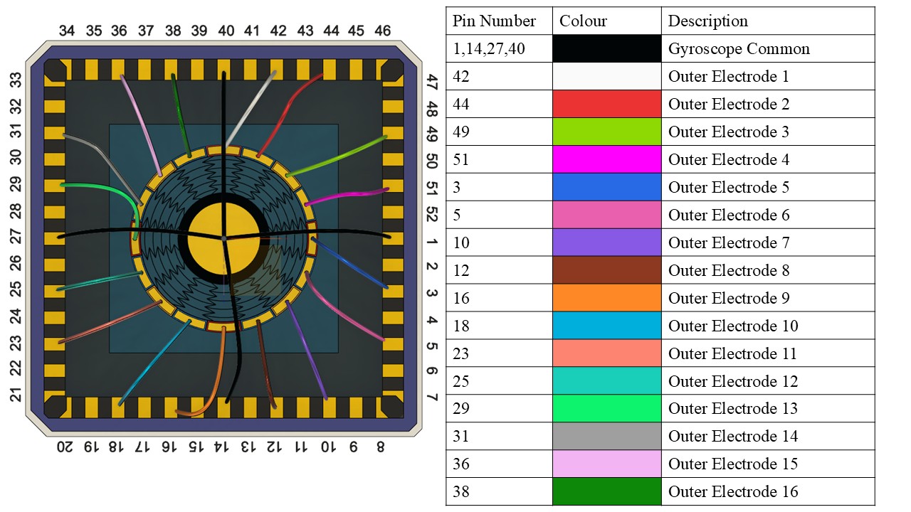
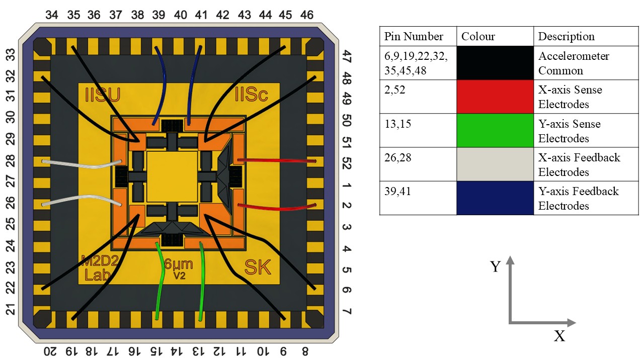
Wire bonding connected the MEMS die pads to the PCB carrier for electrical interfacing.
Process SOI microfabrication steps
- Start with SOI wafer (60 µm device layer, 2 µm BOX)
- Photolithography for device patterning
- Deep reactive ion etching (DRIE) through device layer
- HF vapor release of buried oxide
- Critical point drying to prevent stiction
- Metal deposition for electrodes and bond pads
Info Pinout details
Test Setup
The fabricated ADRG was characterized using a Polytec MSA-500 Micro System Analyzer (Laser Doppler Vibrometer) at atmospheric pressure and room temperature.
Method How the measurement worked
Equipment Full test equipment list
- Polytec MSA-500 Micro System Analyzer
- Keysight 33500B Waveform Generator
- Stanford Research SR830 Lock-in Amplifier
- Keithley 2400 SourceMeter (DC bias)
- Custom vacuum chamber (for Q-factor measurements)
Results
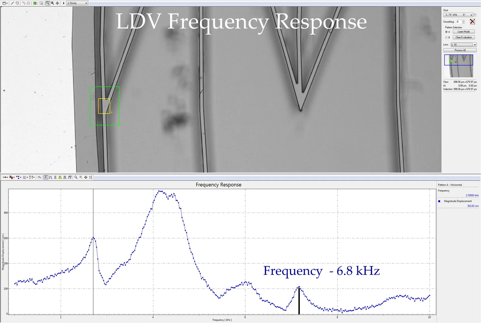
The target was under 5%, and the simulations held up once the devices were made.
Key Finding ADRG performance advantages
- ADRG achieved highest quality factor (181.55k) among five DRG topologies tested
- ADRG demonstrated best relative sense capacitance (46.44% ΔC₀/C₀)
- Mechanical sensitivity of 12.1×10⁻⁶ µm/rad/s: 3-4× higher than prior designs
- LDV validation showed <5% eigenfrequency error between simulation and measurement
Publication Conference paper details
The paper presents a comparison of five DRG topologies (DRG, HDRG, CDRG, GDRG, ADRG) across mechanical sensitivity, Q factor, capacitance change, and Brownian noise floor metrics.
Where Simulation and Reality Disagreed
The hardest part was the gap between the capacitance I simulated and the capacitance we measured on real devices. The resonant frequencies came out within 5% of the COMSOL predictions, but capacitance varied a lot more, so I couldn't take the simulated sensing numbers at face value. Working out how far to trust the model, and designing with that margin in mind, was the biggest lesson of the project.
Full Report
Conference presentation slides.
Skills Technical skills demonstrated
- Simulation: COMSOL Multiphysics, FEM eigenfrequency/thermoelastic analysis
- CAD/Layout: CleWin, KLayout, mask design, DRC
- Fabrication: SOI micromachining, DRIE, HF vapor release
- Characterization: LDV, impedance analysis, wire bonding
- Analysis: MATLAB, Python data processing
Team Contributions & credits
I led parametric design optimization for both sensors, performed COMSOL multiphysics simulations achieving <5% eigenfrequency error, generated CleWin/KLayout fabrication masks, designed wire bonding pinouts, and first-authored the ICMNS 2024 conference paper.
Guided by Prof. G K Ananthasuresh and Karthik Raveendranath (ISRO), with simulation support from Sai Kumar and Suman Acharya, and fabrication by Sudhanshu Shekhar.
Funded by ISRO; fabricated and characterized at CeNSE.