Haptic Knee Brace
Wearable haptic brace providing directional vibrotactile feedback for ACL rehabilitation, guiding users toward stable knee positions without constraining movement.
What I did
- Designed the electronics: Arduino Mega + Nano link, transistor drivers for 6 vibration motors and a connectorised harness
- Integrated 3 flex sensors with calibration for 5°/8° bend detection, in 3D-printed TPU and PLA housings
- Defined the directional vibration logic the team coded, and co-ran user studies
Problem Statement
Knee instability from ACL injuries affects 80,000–120,000 people annually in the US. Current rehabilitation methods face a tradeoff.
- Over-bracing risk: Passive braces limit movement, which leads to muscle atrophy
- Under-bracing risk: Free movement during recovery risks re-injury
- Dynamic valgus: Lateral knee collapse during movement is primary injury mechanism
- Gap: No device provides active guidance without physical constraint
Methodology
Complete wearable system with sensing, actuation, and closed-loop control.
Design & Fabrication
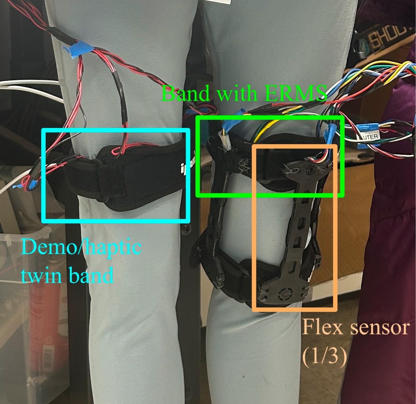
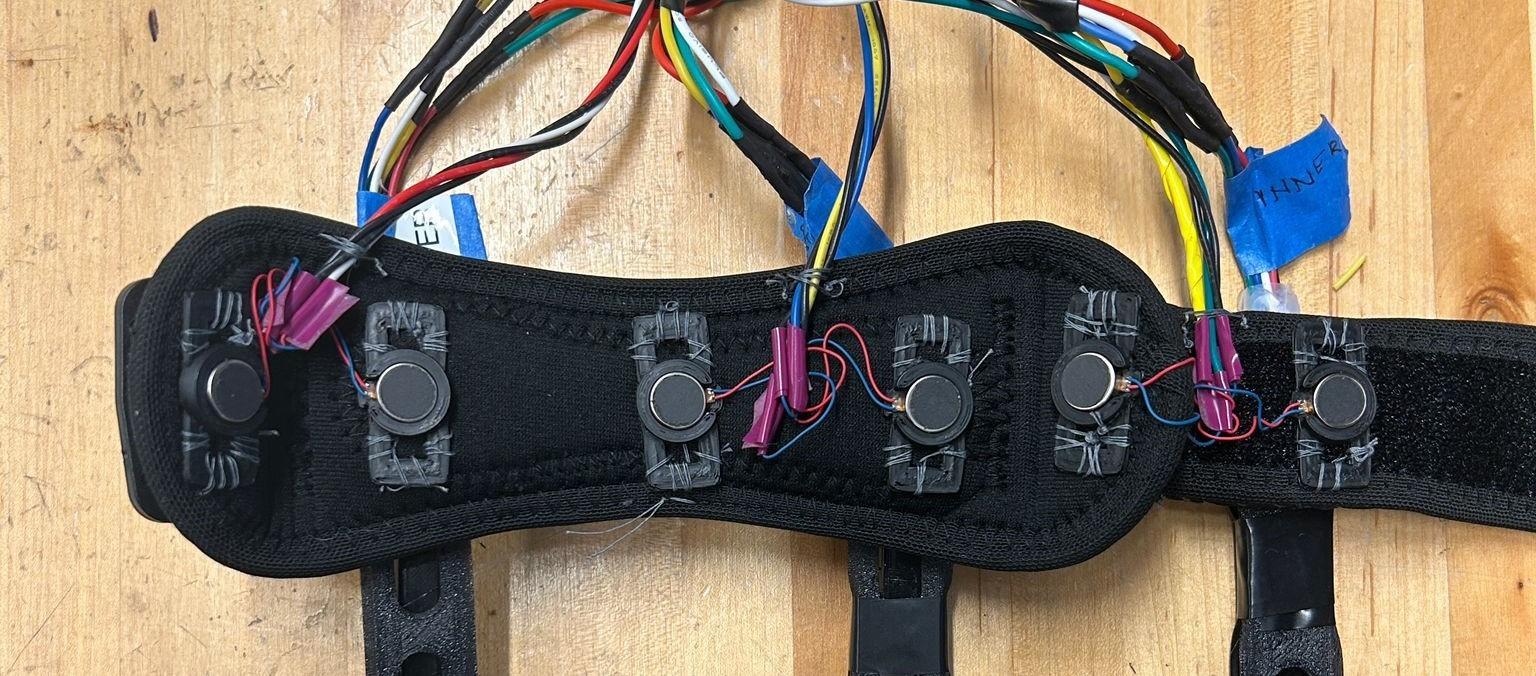
The device consists of two adjustable bands: a lower band with flex sensors around the knee and an upper band with the ERM motor array on the thigh.
- Flex sensors: 3D-printed TPU enclosures for durability and compliance
- ERM motors: 1020-type, 79–183 Hz frequency range, 40mm spacing for ≥75% discrimination
- Bands: Adjustable elastic with Velcro attachment
Electronics Architecture
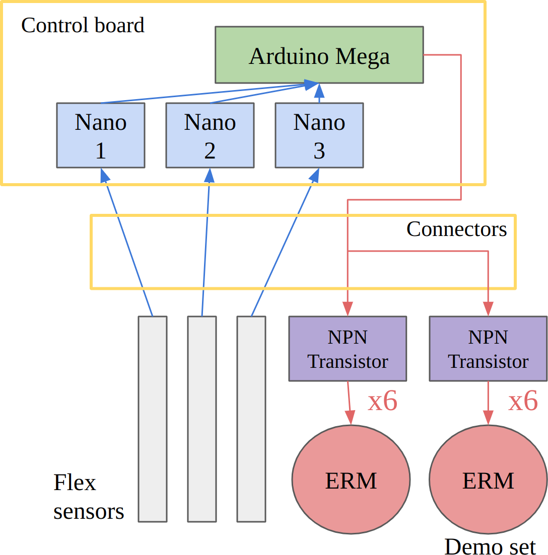
The system uses an Arduino Mega as the main controller, commanding all ERM motors and receiving data from ELEGOO Nano boards that interface with each flex sensor.
- Main controller: Arduino Mega for motor control and data aggregation
- Sensor interface: ELEGOO Nano boards for each flex sensor
- Motor drivers: 2N2221A NPN transistors, PWM-controlled
- Wiring: Two perfboards with connectorized bundles for serviceability
Control Logic
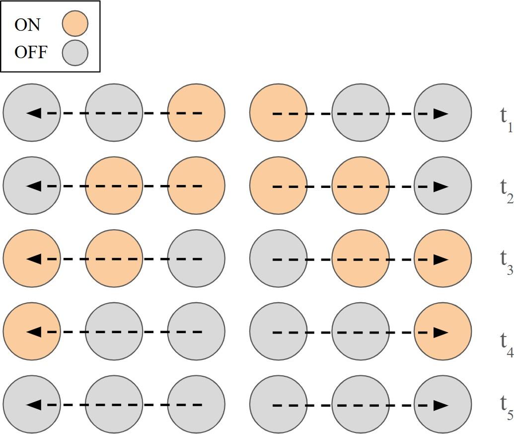
Threshold-based detection with staggered "follow me" vibration patterns that intuitively guide users toward stability.
- Detection: Flex sensors detect knee angle across sagittal, abduction, and adduction planes
- Thresholds: 5° triggers warning, 8° triggers active correction feedback
- Feedback: Staggered "tracing" vibration pattern guides user directionally
- Calibration: Auto-calibration routine on startup for per-user adaptation
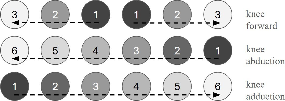

Test Setup
Preliminary vibrotactile perception studies determined optimal design parameters.
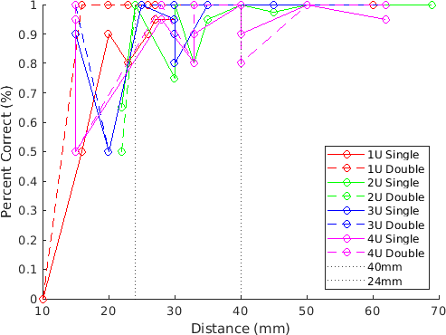
- Two-point discrimination: Testing across 4 knee regions established 40mm motor spacing
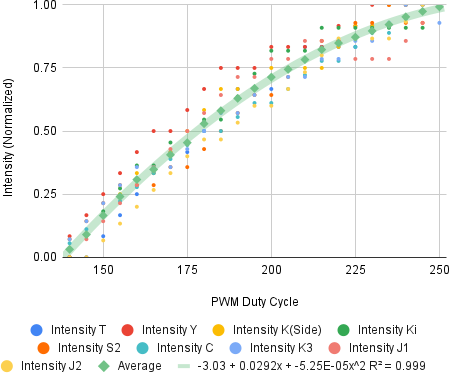
- Intensity perception: Characterized nonlinear PWM-to-sensation relationship
- Device validation: Tested on 2 individuals with uninjured knees
- Haptic demos: 30+ subjects using haptic twin configuration for safe manipulation
Results
Data Key findings from testing
- 100% accuracy: Front knee bend detection and haptic triggering
- 50% accuracy: Compounded abduction direction (requires per-user calibration)
- ≥75% discrimination: Achieved above 24mm spacing, near-perfect above 40mm
- R²=0.999: Intensity perception follows 2nd-order polynomial curve
- 6% knismesis: Subjects experienced tickling sensation preventing response
- Clothing: Vibration perceivable through clothing with no significant damping
Table Two-point discrimination by region
| Region | Location | 24mm Accuracy | 40mm Accuracy |
|---|---|---|---|
| 1U | Front | ≥75% | ~100% |
| 2U | Outer | ≥75% | ~100% |
| 3U | Back | ≥75% | Variable |
| 4U | Inner | ≥75% | ~100% |
Future Planned improvements
- Voice coils: Replace ERMs for finer frequency control
- 2-axis flex sensors: Better abduction/adduction detection
- Accordion TPU mounts: Improved mechanical compliance
- Formal user study: IRB-approved clinical validation
Demo Video
Demonstration of the KICD device mounted on a teddy bear mannequin, showing flex sensor detection of incorrect knee positions and corresponding directional haptic feedback response.
Wearing It
Wearing it was interesting, and you could clearly feel the vibration cues. What we couldn't do was feel it working as intended, because none of us have knees that bend in the direction the device is meant to correct.
Full Report
Complete technical report with methodology, results, and analysis from the 535.691 Haptic Interface Design course final project.
Skills Technical skills demonstrated
- Electronics: Arduino, transistor motor drivers, PWM control
- Fabrication: 3D printing (TPU), wearable integration
- Haptics: Vibrotactile perception, two-point discrimination
- User Studies: Perception testing, data analysis